There are a variety of ways to specify the amplitude of a waveform. Here are a few of the most common forms and a primer on when specific types are most appropriate.
In physics. amplitude is the absolute value of the maximum displacement from zero during one period of an oscillation. In electrical waveforms, amplitude is the maximum deviation of a time-varying voltage from its average value. Confusion can arise because waveform “average value” can be calculated in more than one way.
A typical digital arbitrary function generator (AFG) uses a default amplitude for its output of 1.000 Vpp or peak-to-peak. The default parameters for other waveforms differ. The only parameters for noise, for example, are amplitude and offset. The only parameter for dc is offset.
A more general definition of amplitude in the context of electrical waveforms is a function of the difference between its extreme values within an arbitrary amount of time or number of periods. An oscilloscope, in the time domain mode, displays amplitude of a sine wave unambiguously. It may be shown on a linear or on a logarithmic scale as vertical distance at any given instant between the X-axis and moving trace.
Peak-to-peak amplitude (App) is easy to measure in an oscilloscope time-domain display. Just run a pair of horizontal cursors, moving them to touch the positive and negative peaks. In the measurement box you see the values. Usually, the positive and negative peaks are equidistant from the X-axis, but not always. For example, peaks could be at +3 V and +9 V with the midpoint at +6 V. The user can adjust the Offset at the AFG supplying the signal, changing the average but not the peak-to-peak voltage. Switching the coupling mode in the oscilloscope from dc (the default) to ac eliminates the dc so ripple in, say, a dc power supply output can be more easily measured.
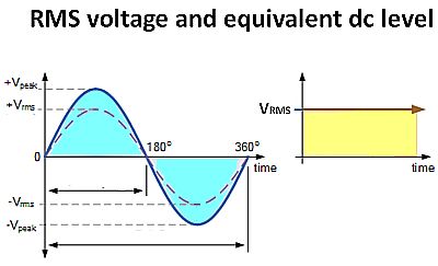 Root mean square (RMS) is the usual mode for measuring ac electrical current or voltage. It is close, but not the same as average or mean power. The reason RMS is widely used is that ac RMS voltages and current cause the same heating effect, i.e. heat dissipation, as equivalent dc voltages and currents, given the same resistive loads.
To make matters somewhat more confusing, the equivalent RMS voltage value of an ac sinusoidal waveform that supplies the same electrical power to a given load as an equivalent dc circuit is sometimes called the “effective value,” Veff or Ieff.
A point to note is that this equivalence is not applicable for non-linear loads. Moreover, even in purely resistive loads it doesn’t apply at high frequencies because of the skin effect, which causes charge carriers to migrate away from the center of a conductor. For frequencies in the range of utility ac, it’s RMS that is valid in measuring amplitude, and that’s how multimeters are calibrated. (Bench-type multimeters generally give accurate RMS readings to about 1 kHz. For higher frequencies, power up your oscilloscope.)
The calculation of RMS voltage for a sinusoidal waveform is generally defined as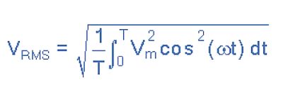
where Vm is the maximum waveform voltage and the waveform itself is Vmcos(ωt). For a sinusoidal waveform, the equation for RMS voltage reduces to Vpk(1/√2)=Vpk×0.7071. It is also easy to find VRMS formulas for common waveform shapes such as triangle, square, and sawtooth. More complicated waveforms require an integration over the waveform period. Fortunately, many modern oscilloscopes can make this calculation and can display the RMS value.
 That brings us to the average value of a waveform. For a periodic waveform, the area above the horizontal axis is positive while the area below the horizontal axis is negative. The result is that the average or mean value of a symmetrical alternating quantity is zero; the area above the horizontal axis equals that of the area below the axis and thus cancel each other out. To come up with a meaningful average or mean value of a symmetrical alternating quantity, such as a sine wave, the convention is to measure the average value over only one half a cycle, because the average value over one complete cycle is zero regardless of the peak amplitude.
But note the word ‘symmetrical.’ Many waveforms used in modern electronics are anything but symmetrical. So average values have some meaning in these instances. The symbols often used for representing an average value are VAV or IAV.
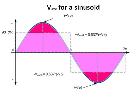
The VAV of a sinusoidal waveform is determined by multiplying the peak voltage by the constant 0.637, which is 2/π. But note this is for a sinusoid. The more general equation for VAV consists of the integral over the half-cycle of the voltage waveform Ψ :
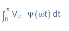
As in the case of RMS voltages, it’s easy to find equations giving the VAV for routine triangle, sawtooth, and square waveforms. The more non-symmetrical the waveform, the more complicated is the integral. But as the complexity of the waveform of interest grows, the concept of VAV starts to lose meaning.
To compare the relative amplitudes of two signals, decibels (dBs) are used. It would be equally correct to say, for example, that one signal has seven times the amplitude of another, but this becomes unwieldy because often we are talking about a signal that is thousands, millions or billions of times greater than the reference signal. Such is the rationale for stating the ratio of signal amplitudes in decibels. The ratio of amplitudes of any two signals is:
dB = 10 log10 P2/P1
where P1 and P2 are the powers of the two signals. A signal that is double the amplitude of another is roughly +6 dB relative to it because log10 2 = 0.3010. A signal having 10 times the amplitude of another signal is +20 dB relative to it. A signal having an amplitude of 1/10 that of another is -20 dB relative to it.
There are times that a decibel value is used to denote the amplitude of a single signal rather than comparing two signals. In these instances, a reference is assumed in the context of the discussion. The reference may be denoted by placing a lower-case letter after dB. For example, dBm means the reference is one milliwatt.

Leave a Reply
You must be logged in to post a comment.