The oscilloscope can be viewed as essentially a voltmeter that incorporates a dynamic display. But the oscilloscope can also make use of a current probe to convert current information into corresponding voltage potentials displayed in units of Amperes. The current-to-voltage conversion takes place within the current probe which operates like the electrician’s clamp-on ammeter.
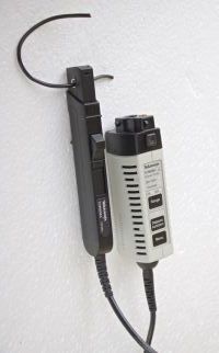
The ac current probe working in conjunction with a Tektronix MDO3000 Oscilloscope is typical of many such devices in that it must be degaussed periodically. This is because the jaws can act as a permanent magnet and become magnetized with use. To degauss a current probe, the operator inserts the connector into an analog channel input. There should be no powered conductor in the jaws, and they should be locked in the closed position to complete the magnetic circuit. A window appears, alerting the user if degaussing is required. If so, a press of the degauss button on the probe body performs the procedure automatically. What happens behind the scene is that an ac current is applied and is gradually diminished to zero, demagnetizing the jaws. {Old-time audiophiles who owned high-end tape decks may recognize the procedure because magnetic tape heads periodically needed a similar treatment.}
The operator clamps the jaws around the ac current-carrying wire to make a measurement. The conductor need not be exactly centered. It can pass through the jaws at an angle because the magnetic field will be averaged with respect to the pick-up coil as long as the jaws are closed. As described by Faraday’s Induction Law, the ac current flowing through the conductor establishes an oscillating magnetic field around it. When the jaws are securely closed, a voltage appears across a winding in the current probe, and this is what the oscilloscope measures.
If the ac current under investigation is too small for the probe to measure, it can be multiplied by coiling the conductor so that it passes in the same direction more than once through the jaws. Then, the quantity displayed in the oscilloscope must be divided by the number of turns in the winding through the jaws. Of course, a cable containing a live wire and a return conductor cannot be measured, because the ac currents flowing in opposite directions would cancel out.
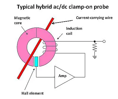 Inductive probes can only sense ac. To sense dc or super low-frequency ac, one needs a clamp incorporating a Hall effect sensor. A Hall effect sensor varies its output voltage in response to a magnetic field. Hybrid ac/dc current probes are also available that incorporate both a Hall-effect sensor element and a current transformer.
Clamp-on probes able to handle tens to thousands of amperes of ac current are Rogowski current probes. A Rogowski coil has a flexible clip-around sensor coil designed to wrap around the current-carrying conductor. The Rogowski coil is similar to an ac current transformer in that a voltage is induced into a secondary coil that is proportional to the current flow through an isolated conductor. The key difference is that the Rogowski coil has an air core rather than a high-permeability steel core. The air core design 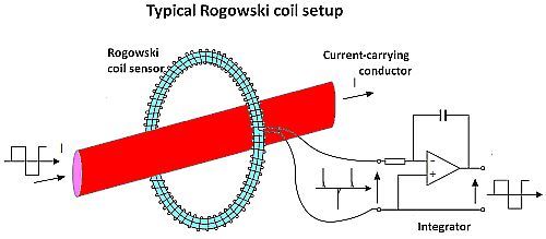 has a lower insertion impedance than a magnetic core which enables a faster signal response. As with inductive clamps, the air-cored coil goes around the current-carrying conductor and the magnetic field produced by the ac current induces a voltage in the coil. The Rogowski coil produces a voltage that is proportional to the rate of change (derivative) of the current enclosed by the coil-loop. The coil voltage is then integrated to provide an output voltage proportional to the input current signal.
Of course, there is another way to measure current in the absence of a probe: Place a resistor in series with the load and measure the voltage across it. The advantages in using the current probe are:
•You don’t have to cut open (and later resolder) the circuit.
•The series resistor reduces the current slightly, making for an inaccurate reading and possibly disabling the circuit.
•Using the current probe, the amount of current can be read directly, rather than calculated.
To measure high power levels with an oscilloscope, first verify voltage limits will not be exceeded. Then, using a 10:1 voltage probe, configure one channel to measure voltage. In the same circuit, configure a second channel to measure current, hopefully using the current probe. Even inexpensive scopes these days have a math function that can multiply the two channels together to yield the product, expressed in decibels, showing the amount of power in the circuit (P=E×I).
A scope equipped with a current probe and voltage probe can also be used to measure power factor in a small load so long as the conductor’s ampacity does not exceed the size limit of the clamp-on probe. The measurement starts with the connection of a passive (usually 10:1) voltage probe across the load and the current probe clamped around one of the conductors. The screen is set up to display current and voltage waveforms. In a purely resistive load, the sine waves are in phase. What this means is that the negative- and positive-going peaks occur at the same point in time. In this case, the power factor is +1, which is good in the sense that all the power in the utility-provided circuit is available to perform work for the customer.
When the load is inductive, current lags the applied voltage, and when the load is capacitive, current leads the applied voltage. Either of these are considered low, or poor power factor, and they are harmful from the point of view of the utility and from the point of view of the customer. Unproductive power does not register on the meter and larger conductors are required for heat dissipation.
Inductive loads, such as motors and fluorescent ballasts, are far more common than capacitive loads in commercial and industrial settings. Both equate to poor power factor. These loads, however, can be added with opposite signs algebraically, and thus power correction capacitors are often installed to improve power factor.
A problem with passive probes is that they have a relatively high input capacitance that causes circuit loading at high frequencies or with low-frequency signals containing high-frequency content. Consequently, active probes are preferable for measuring and displaying signals faster than 500 MHz or when measuring a high-impedance circuit. Active probes have high resistance at the probe tip but terminate into the 50-Ω input of the oscilloscope.

Active FET probes provide high impedance out to about 1.5 GHz (typical) thanks to their low capacitance. An active probe uses an FET or MOSFET at its input, so the probe is nearly invisible to the device under investigation. The input capacitance is not much over 1 pF. The active probe is typically powered through a specialized connector at the oscilloscope so it doesn’t siphon off power from the circuit under investigation. (Consequently, the specialized connector means active probes typically only work with the brand of scope for which they were designed.)
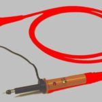
High-voltage probes are characterized by large probe bodies and barrier discs that protect the user from contact with the highly energized object of inquiry. The large body and barrier also resist the flow of charge carriers, which tend to travel along the surface. Some high-voltage probe bodies are filled with liquid fluorocarbon, which displaces more conductive air that otherwise would surround the series resistor.
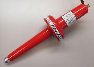
These measures are necessary because maximum voltage can exceed 100 kV, and coronal discharge becomes an issue.
Oscilloscope manufacturers offer highly specialized low- and high-bandwidth optical probes that facilitate acquisition of high-speed serial data signals. These probes are intended to be used as test and measurement tools for general-purpose characterization of ultra-fast optical signals and for physical layer conformance testing of high bit rate, fiber optic time-domain optical signals such as 100 Gb/sec and 400 Gb/sec telecommunication or data communication signals. It is to be stressed that these optical probes can only be used with compatible oscilloscopes. To use the optical probe, specialized firmware, available at the manufacturer’s website, must be installed in the oscilloscope.
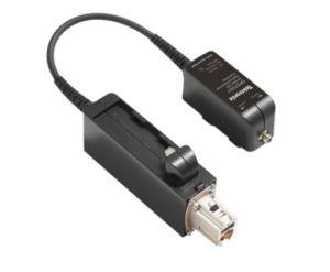
The procedure for connecting optical signals to the probe involves cleaning all optical fiber connectors before making connections. Optical fiber connector end-face contamination is a leading cause of optical fiber failures. Contaminants cause insertion loss and back-reflection that inhibits optical transmission. Because dirt can be an issue before, during and after fiber optic certification testing, and such dirt can migrate from one optical fiber connector end-face to another upon mating, both sides of any connection must be cleaned and inspected before making a connection. Further, mating contaminated optical fiber connectors can cause permanent damage as microscopic debris is crushed between end-faces upon physical contact. It is recommended to use a fiber optic inspection scope to check for contamination before connections are made.
To maintain high performance (low return loss) connect an adapter and cable between the input of the O/E connector and the device under test. When you make connections to other devices, leave the adapter and cable in place to protect the O/E converter from wear.
If you connect fiber cores larger than the maximum diameter for the probe model, the O/E converters may still couple light, but the mismatch in core diameters will cause lower conversion gain.


Leave a Reply
You must be logged in to post a comment.