All rotary electric motors, ac, and dc, operate because of the interaction of two magnetic fields. One is stationary and is (usually) associated with the motor’s outer enclosure. The other rotates and is associated with the motor’s spinning armature (also called its rotor). Rotation is caused by the interaction between the two fields.
In a simple dc motor, there is a rotating magnetic field whose polarity is reversed every half turn by means of a brush-commutator combination. Brushes — basically conductive carbon rods which brush against the conductors on the rotor as they turn — also serve the purpose of getting the electrical current into the spinning armature. The situation is a bit different in the dc brushless motor. The rotating field is still reversed but by a commutation that takes place electronically.
An induction motor has the unique quality that there is no electrical connection between the stationary and rotating windings. Utility ac is applied to the motor’s terminals and powers the stationary windings.
All induction motors are asynchronous motors. The asynchronous moniker arises from the slip between the rotational speed of the stator field and somewhat slower speed of the rotor.
Most modern induction motors have a rotor in the form of a squirrel cage. The cylindrical squirrel cage consists of heavy copper, aluminum, or brass bars set into grooves and connected at both ends by conductive rings that electrically short the bars together. The solid core of the rotor is built from stacks of electrical steel laminations.
It is also possible to find induction motors containing rotors made up of windings rather than a squirrel cage. These are called wound-rotor induction motors. The point of the construction is to provide a means of reducing the rotor current as the motor first begins to spin. This is generally accomplished by connecting each rotor winding to a resistor in series. The windings receive current through some kind of slip-ring arrangement. Once the rotor reaches final speed, the rotor poles get switched to a short circuit, thus becoming electrically the same as a squirrel cage rotor.
The stationary part of the induction motor windings (stator) connects to the ac supply. Applying a voltage to the stator causes an ac current to flow in the stator windings. The current flow induces a magnetic field which affects the rotor, setting up voltage and current flow in the rotor elements.
A north pole in the stator induces a south pole in the rotor. But the location of the stator pole rotates as the ac voltage varies in amplitude and polarity. The induced pole in the rotor attempts to follow the rotating stator pole. However, Faraday’s law says that an electromotive force is generated when a loop of wire moves from a region of low magnetic-field strength to one of high magnetic-field strength, and vice versa. If the rotor exactly followed the moving stator pole, there would be no change in magnetic field strength. Thus, the rotor always lags behind the stator field rotation because the rotor field always lags behind the stator field by some amount. This lag causes the rotor to rotate at a speed that is somewhat slower than that of the stator field. The difference between the two is called the slip.
The amount of slip can vary. It depends principally on the load the motor drives, but also is affected by the resistance of the rotor circuit and the strength of the field that the stator flux induces. Slip in a Design B motor ranges from 0.5% to 5%.
When the motor is standing still, the rotor and stator windings are in effect primary and secondary windings of a transformer. When ac is initially applied to the stator, the rotor isn’t moving. So the voltage induced in the rotor has the same frequency as that of the stator. As the rotor starts spinning, the frequency of the voltage induced in it, fr, drops. If f is the stator voltage frequency, then slip, s, relates the two via fr = sf. Here s is expressed as a decimal.
Because an induction motor has no brushes, commutator or similar moving parts, it is less expensive to manufacture and maintain than other types of motors.
In contrast, consider a synchronous motor. Here, the rotor turns at the same rate — that is, in synchronization — as the stator’s magnetic field. Like the induction motor, the synchronous ac motor also contains a stator and a rotor. The stator windings also connect to the ac power as in an induction motor. The stator magnetic field rotates in sync with the line frequency.
The rotor winding in a synchronous motor may receive current in a variety of ways, but usually not by induction (except in some designs, only to provide start-up torque). The fact that the rotor turns in synch with the ac line frequency makes the synchronous motor useful for driving highly-accurate clocks.
We must emphasize that a synchronous ac motor rotor turns in synch with an integral number of ac cycles. This is not the same as saying that it turns at an RPM equal to the line frequency. The RPM of the motor rotor, i.e. the synchronous speed N, is:
N = 120f/P = 60 f/P
Where f is the frequency of the ac supply in Hz, P is the number of poles (per phase), and p is pair number of poles per phase.
Accordingly, the more poles, the slower the synchronous motor turns. It is more expensive to build a slower motor, given equal horsepower. At 60 Hz:
- A two-pole/phase synchronous ac motor turns at 3,600 RPM.
- A four-pole/phase synchronous ac motor turns at 1,800 RPM.
- A six-pole/phase synchronous ac motor turns at 1,200 RPM.
- An eight-pole/phase synchronous ac motor turns at 900 RPM
- A ten-pole/phase synchronous ac motor turns at 720 RPM.
- A twelve-pole/phase synchronous ac motor turns at 600 RPM.
Low fractional-horsepower synchronous ac motors are useful where precise timing is desired. High-horsepower synchronous ac motors, while more expensive than three-phase induction motors, have two additional qualities. Despite the higher initial cost, they may be worthwhile in the long run because they are more energy efficient than other types of motors. Second, sometimes concurrently, they can operate at leading or unity power factor, so one or more synchronous ac motors can provide power-factor correction while also performing useful work.
There are several distinct types of ac synchronous motors. They are generally classified according to their means of generating a magnetic field. Separately excited motors have magnetic poles energized by an external source. In contrast, the magnetic poles are energized by the motor itself in a self-excited (also sometimes called non-excited and directly excited) machine. Non-excited types include reluctance motors, hysteresis motors, and permanent-magnet motors. Additionally, there are dc-excited motors.
Non-excited synchronous motors have steel rotors. In operation, the rotor is magnetized with the required magnetic poles in a manner analogous to that of an induction motor. But the rotor turns at the same speed and in synch with the stator rotating magnetic field. The reason is there are slots in the rotor. The motors start as induction motors. When they approach synchronous speed, the slots enable the synchronous magnetic field to lock onto the rotor. The motor then turns at synchronous speed so long as the required torque is low.
In the reluctance motor, the rotor has projecting poles that resemble individual teeth. There are fewer rotor than stator poles, preventing stator and rotor poles from aligning, in which event there would be no rotation. Reluctance motors are not self-starting. For this reason, special windings (called squirrel-cage windings) are frequently built into the rotor, so the reluctance motor starts as an induction motor.
The hysteresis motor takes advantage of the wide hysteresis loop in the high-coercivity cobalt-steel rotor. Due to the hysteresis, the phase of magnetization in the rotor lags behind the phase of the stator rotating magnetic field. This lag creates torque. At synchronous speed, rotor and stator fields lock in to produce continuous rotation. One advantage in the hysteresis motor is that it is self-starting.
A permanent-magnet ac synchronous motor has permanent magnets embedded in the rotor. The latest elevators are powered by these motors, and a gearbox is not required.
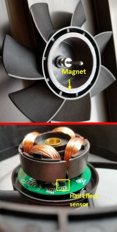
The directly excited synchronous motor may be called by various names, including ECPM (electronically commutated permanent magnet), BLDC (brushless dc), or just a brushless permanent-magnet motor. The rotor contains permanent magnets. The magnets may mount on the rotor surface or be inserted within the rotor assembly (in which case the motor is called an interior permanent-magnet motor).
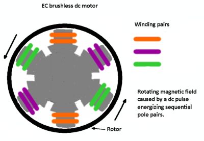
A computer controls sequential switching of power on the stator windings at the proper time using solid-state switches. Power is applied to coils wound on stator teeth, and if a salient pole of the rotor is aligned perfectly with the stator tooth, there is no torque produced. If the rotor tooth is at some angle to the stator tooth, at least some magnetic flux crosses the gap at an angle that is not perpendicular to the tooth surfaces. The result is a torque on the rotor. Thus, switching power to stator windings at the right time causes a flux pattern that results in either clockwise or counterclockwise motion.
One other type of synchronous motor is the switched reluctance (SR) motor.
Its rotor consists of stacked steel laminations with a series of teeth. The teeth are magnetically permeable and the areas surrounding them are weakly permeable by virtue of slots cut into them.
Unlike induction motors, there are no rotor bars and consequently no torque-producing current flow in the rotor. The absence of any form of conductor on the SR rotor means that overall rotor losses are considerably lower than in other motors incorporating rotors carrying conductors.
The torque produced by the SR motor is controlled by adjusting the magnitude of current in the stator electromagnets. Speed is then controlled by modulating the torque (via winding current). The technique is analogous to the way speed is controlled via armature current in a traditional brush-dc motor.
An SR motor produces torque proportional to the amount of current put into its windings. Torque production is unaffected by motor speed. This is unlike ac-induction motors where, at high rotational speeds in the field-weakening region, rotor current increasingly lags the rotating field as motor RPM rises.
Finally, there is the dc-excited ac synchronous motor. It requires a rectified power supply to generate a magnetic field. These motors are generally built in sizes larger than one horsepower.


Nice article!
It’s good to know that highly-accurate clocks can be run easily with a synchronous motor because it turns in sync with the ac line frequency. I had no idea that synchronous motors were like this or what they were good for. I hope that more people can learn about the uses for these motors so that they maybe we can use more of them.
A very informative article. Thanks for a good job.