The concepts of signal phase modulation and signal frequency modulation, and the difference between them, are often a source of confusion. Ditto for the related idea of phase distortion. Here, we’ll try to clarify things.
To understand phase distortion, recall that any waveform can be considered to be a sum of sine waves of different amplitudes and frequencies. Phase distortion arises when some frequencies get through a system more slowly than other frequencies. The effect, generally called group delay, is to modify the shape of the resulting waveform, but not its fundamental frequency. This change in shape is considered a phase distortion.
To complicate matters somewhat, the term phase distortion is sometimes applied to the case where a reactive component changes the relationship between instantaneous current and voltage. If the load is purely resistive, the applied voltage and current are in phase. If the load is reactive, meaning that it is either capacitive or inductive, the voltage and current waveforms are no longer in phase. A point to note about the phase shift caused by purely reactive components is that the shape of the pure sine wave doesn’t change.
In a capacitive circuit, the current leads the voltage. It happens that the impedance in a capacitive circuit is minimum when the rate-of-change of the applied voltage is greatest, and it is maximum when the rate of change is least. A capacitive circuit reacts not to the voltage level, but to the rate of change. That is why current is said to lead voltage in a capacitive circuit. Similarly, an inductive circuit impedes current flow the most when the rate-of-change is greatest, and it impedes the least when the rate-of-change is lowest. The way to think of it is that as applied voltage in an inductive circuit rises, energy is temporarily stored in the magnetic field that is being established around the conductive elements, and as it falls, that energy is fed back into the conductive elements, in both cases opposing the change in voltage. That is why current is said to lag voltage in an inductive circuit.
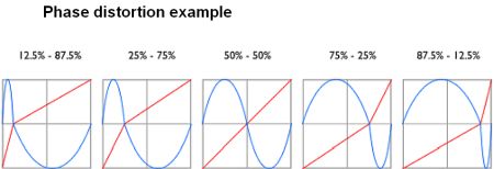
Finally, there is a technique called phase distortion synthesis introduced in the 1980s by Casio in its music synthesizers. The concept can be a bit confusing because Casio modulated a carrier (i.e. an audio tone) with another waveform, but did so in a manner that distorted each cycle of the carrier without changing its frequency. The modulators were various angular waves that ‘distorted’ the carrier by changing the point in time of its first zero crossing within each full waveform period. The same technique is now available in various music generator ICs.
That brings us to phase modulation and frequency modulation. Both modulation techniques are classified as angle modulation techniques. Angle modulation affects the phase angle (and thus the frequency) of the signal. With phase modulation, the change of the phase angle is proportional to the message that is to be modulated onto the signal. In contrast, the instantaneous change in frequency is proportional to the message that is to be modulated onto the signal in frequency modulation.
In phase modulation, the modulation index h (i.e. the degree of modulation) is directly proportional to the modulating voltage only while in frequency modulation, the modulation index is also inversely proportional to the modulating frequency.
For PM:
h =Kθ
where K is constant of proportionality, θ is modulating voltage amplitude.
For FM:
h = ∆f/F
where ∆f= maximum frequency deviation, F = the modulating frequency. Therefore, when modulating frequency changes, the PM modulation index will remain constant, whereas the FM modulation index will rise as modulating frequency diminishes and vice versa.
There are a few misunderstandings about FM and PM that may lead to some confusion. The primary belief is that FM solely modulates the frequency and keeps a constant phase angle while PM keeps a constant frequency and the phase angle is modulated. As a practical matter, it is tough to keep a constant frequency while changing the phase angle (and vice versa). A change in phase angle always causes an instantaneous change in frequency and a change in frequency must cause an instantaneous change of the phase angle. Here the word “instantaneous” is important as “rate of change” and “instantaneous rate of change” are two completely different things.
Phase modulation is capable of conveying analog information but it is more suitable for digital transmission in which it is widely used. It comprises the contextual framework for schemes that include phase shift keying (PSK), binary phase shift keying (BPSK), quadrature phase shift keying (QPSK), eight-point phase-shift keying (8PSK), sixteen-point phase shift keying (16PSK) and offset phase shift keying (OPSK).


Leave a Reply
You must be logged in to post a comment.