DIY and commercial RF current probes let you find which cables act as EMI-emitting antennas.
RF current probes are one of my most useful troubleshooting tools. Because most radiated emissions failures are due to attached cables acting as transmitting antennas, clamping an RF current probe around a wire or cable will measure the common mode harmonic RF currents flowing in the wire or cable that causes this emission.
Current probes typically use a toroidal core of broadband ferrite or similar material and are simply an RF transformer with the measured wire or cable as the primary winding and the measuring port as the secondary (Figure 1). The probe’s frequency range and sensitivity will depend on the type of material used and the number of turns of wire wound around the core. Most commercial RF current probes are calibrated from 10 kHz to 200 MHz or 250 MHz, with some designed and calibrated up to 1000 MHz. Most common-mode currents fall from 30 MHz to 300 MHz.

On emission-only probes, a resistive network controls the impedance, which flattens the response. This response is known as the transfer impedance or transducer factor. Similar higher-power-rated current probes (less the resistive network) can inject RF energy into a cable and are called bulk current injection (BCI) probes. You can use them for conducted RF immunity tests.
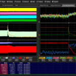
You can use RF current probes with either spectrum analyzers (frequency domain) or oscilloscopes (time domain). Most engineers doing emissions troubleshooting use a spectrum analyzer while troubleshooting pulse-type issues such as ESD are best measured using an oscilloscope.
Measuring current on I/O or power cables can indicate which cables may be the main cause of radiated emissions. The reduction of RF currents on those cables can often reduce the radiated emissions from the equipment under test (EUT). Importantly, by knowing the harmonic common-mode current flowing in the cable at a certain frequency, you can calculate the expected E-field emission level and compare to the radiated emission limit. In other words, you can predict pass/fail for a particular cable by simply measuring the RF current through that cable. We’ll cover that calculation in Part 2 of this series.
DIY RF current probes
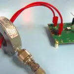
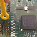
In a pinch, a common “snap-on” ferrite choke may be used as a low-budget RF current probe (Figure 2). Choose a ferrite material that has some impedance in the frequency range of interest (such as Fair-Rite type 31 material) and wind a few turns of wire around one-half. The number of turns is not critical. I generally use 5 to 7 turns.

Connect the wires to an appropriate coaxial connector and then simply clamp the ferrite around the wire or cable to be measured. Because these are not calibrated, they would not be useful for estimating E-field levels, but for general relative “before and after” measurements, they’ll suffice nicely. The objective is to reduce the harmonic common mode currents in any wire or cable attached to your EUT.
Commercial RF current probes
The advantage of most commercial current probes is that they easily clamp around the wire or cable that you want to evaluate. They are calibrated to accurately read RF current. There are many good manufacturers of clamp-on current probes, such as Com-Power, Fischer Custom Communications, Pearson Electronics, Rohde & Schwarz, York, Solar Electronics, and ETS-Lindgren.
The advantage of a commercial current probe is absolute accuracy in order to be able to predict whether a given cable under test will pass or fail the emissions limit. This is a huge advantage to using RF current probes!
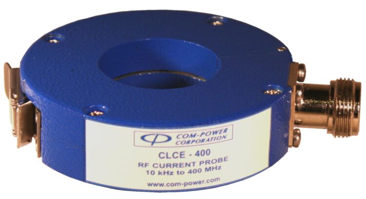
Here are some affordable examples. Com-Power makes a low-cost clamp-on current probe (Figure 3). They come with individual calibration charts and cover the range of 10 kHz to 400 MHz. The price as of this writing is $1,390.
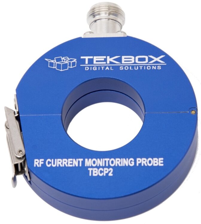
The Tekbox TBCP2 is a clamp-on RF current probe (Figure 4). The probe has a very flat response with a 3 dB bandwidth of 250 MHz, 500 MHz, or 750 MHz, depending on the model. The aperture of the RF current monitoring probe is 32 mm. Its transfer impedance is 12 dBΩ to 15 dBΩ. Price ranges from $619 to $729.
Caution
When using an RF current probe to measure cable currents outside of a shielded room or semi-anechoic chamber, the wire will not only transmit harmonic energy from the EUT into the probe (what we want), but it will act as a receiving antenna and couple in “ambient” transmissions such as radio, TV, cellular, and two-way radio communications (what we don’t want).
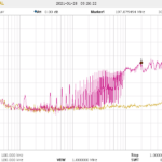
When initially measuring a cable, I’ll disconnect the cable from the EUT, keeping the current probe clamped around it. The cable will serve as a receiving antenna. Then, I’ll place the spectrum analyzer in “Max Hold” mode and capture several sweeps of the ambient activity. I’ll store this trace as my baseline and then activate a second trace for the actual cable measurement after reattaching the cable to the EUT.
Summary
You’ll find a calibrated current probe to be a valuable addition to your troubleshooting kit. If your emissions issues are due to cable radiation, you can perform nearly all the troubleshooting with nothing more than a current probe attached to the cable that’s radiating. In addition, knowing the absolute value of the harmonic current in the cable will let you calculate the E-field emitted at that harmonic frequency, and you’ll be able to predict a pass or fail for radiated emissions based on that current measurement. We’ll cover this in Part 2.
References
The HF Current Probe: Theory & Application
Com-Power
Tekbox
Saelig Electronics (U.S. distributor for Tekbox)
Wyatt, Create Your Own EMC Troubleshooting Kit (Volume 1, 2nd Edition), Amazon, 2022
Wyatt, Workbench Troubleshooting EMC Emissions (Volume 2), Amazon, 2021

Leave a Reply
You must be logged in to post a comment.