In Part 2, you will learn how to use an RF current probe to calculate E-fields and troubleshoot EMI emissions from cables. Free and low-cost software tools let you customize the calculations based on your current probe’s data.
As I mentioned in Part 1, RF current probes are one of my most useful troubleshooting tools. Most radiated emissions failures arise from attached cables acting as transmitting antennas. Clamping an RF current probe around a wire or cable will measure the common-mode harmonic RF currents that cause this emission. If I know that the emission failures are due to cable radiation, an RF current probe and spectrum analyzer may be the only tools required to mitigate the problem.
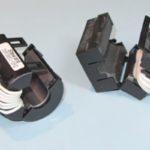
To measure the harmonic currents traveling along a wire or cable, simply clamp the probe around the cable and slide it back and forth to maximize the dominant harmonic peaks (Figure 1). Set the spectrum analyzer from 30 MHz to 500 MHz (or 1000 MHz) and adjust the attenuation and reference levels for a usable display.

Estimate E-fields from cables
As I hinted last time, it’s possible to estimate the E-field at certain harmonic frequencies and at a particular distance from the cable. This measurement can help predict passing or failing a compliance test, assuming that harmonic cable currents are the dominant source of emissions and the length is electrically short compared to a measured wavelength.
All commercial current probes, such as the Fischer Custom Communications F-33-1 I use, include a calibration chart that shows the transfer impedance (Zt, usually in dBΩ) versus frequency (Figure 2). The nearly flat horizontal linear region is the most useful part of the plot, as you can use a constant transfer impedance to calculate the common-mode current in the wire or cable.

Following Ohm’s Law: Where Vout is the measured voltage at the 50 Ω port, and I is the common-mode current in the wire or cable.
We can express this equation in dB: Solving for I (the common mode current through the wire or cable):
 Knowing the common mode current traveling in a wire lets us calculate the expected E-field from this wire or cable based on the following equation (References 4 and 5):
 Where Ec,max is the calculated E-field (V/m), Ic is the measured common mode current (A), f is the harmonic frequency (Hz), L is the length of the wire or cable (m), and d is the measured distance from the wire or cable in meters. Typically, d would be 3 m or 10 m used for radiated emissions compliance tests to compare with test limits in commercial EMC standards.
Calculator tools
To make these calculations easier, I developed the spreadsheet tool shown in Figure 3. Here, it’s customized for the Fischer F-33-1 probe, but knowing ZT in the linear region for your probe, you can simply plug that value (dBΩ) into the “Probe Zt” cell. This tool is available at no cost at emc-seminars.com. Just request it from the author.

You can plot the calculated value of an E-field directly onto the limit chart (Figure 4), assuming you’ve used a distance, d, of 10 m in the calculation in this case.

Alternatively, Andy Eadie developed a more sophisticated spreadsheet tool where you can specify several different current probes and plot the result on the commercial radiated-emission-limit graph (Figure 5). Andy’s calculator also accounts for wires or cables longer than one wavelength (Reference 3 and 6). The spreadsheet is available for a nominal fee.

Summary
The ability to calculate the approximate pass or fail, given the harmonic current measurement of a wire or cable, is a powerful tool when dealing with radiated emissions from a product. When it’s known that cable radiation is the dominant cause of compliance failure, then often, an RF current probe and spectrum analyzer may be the only tools required to troubleshoot and mitigate. If you don’t own an RF current probe, maybe now is the time to consider one.
References
The HF Current Probe: Theory & Application
Com-Power
Tekbox
Saelig Electronics (U.S. distributor for Tekbox)
Wyatt, Create Your Own EMC Troubleshooting Kit (Volume 1, 2nd Edition), Amazon, 2022
Wyatt, Workbench Troubleshooting EMC Emissions (Volume 2), Amazon, 2021
EMC FastPass (Andy Eadie)
Ott, Henry, Electromagnetic Compatibility Engineering, Wiley, 2009
Paul, Clayton, Introduction to Electromagnetic Compatibility (2nd Edition), Wiley Interscience, 2006, pages 518-532.
Radiation from Common Mode Currents – Beyond 1GHz
Wyatt, Kenneth, Create Your Own EMC Troubleshooting Kit (Volume 1, 2nd Edition), Amazon, 2022.

Leave a Reply
You must be logged in to post a comment.