For general troubleshooting, you can use consumer-grade antennas such as for TV. Pre-compliance tests require calibrated antennas.
Antennas are important for capturing radiated harmonic emissions from electronic products. You can use them for simple troubleshooting or for calibrated pre-compliance testing. For troubleshooting purposes, you can use almost any uncalibrated antenna. I’ve even seen engineers use Wi-Fi antennas for detecting emissions from 50 MHz to 200 MHz. If your antenna can sense the emissions, then you can use it for general troubleshooting.
When performing a pre-compliance test, you’re trying to duplicate emissions testing as performed in an EMC test lab. That requires a more expensive calibrated antenna. In this article, I’ll stick to troubleshooting.
Radiated emissions troubleshooting relies more on relative changes than on measuring absolute levels. For example, if you know your product is failing by 4 dB, reducing the problem harmonic by 10 dB at your own facility, as measured with a nearby antenna, should provide a reasonable assurance of passing a compliance test.
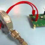
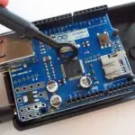
Figure 1 shows how I normally set up a product for troubleshooting radiated emissions. Let’s look at several low-cost choices for troubleshooting.

Low-cost TV antennas
For troubleshooting on a budget, I’ve used small, low-cost antennas such as the “rabbit ears” TV antenna for general-purpose radiated-emissions troubleshooting. These antennas are still available in some TV and electronic parts stores and online. UHF TV “bowtie” antennas also work well from 300 MHz to 800 MHz. To improve performance, add a standard TV 300-Ω-to-75-Ω balun to better match the 50 Ω coax cable (Figure 2). They will perform just fine for troubleshooting purposes. Unfortunately, these antennas are getting harder to find. Other options include DTV antennas and, my favorite, PC-board antennas.

Ever since the US FCC mandated over-the-air (OTA) digital television in 2009, many low-cost aftermarket DTV antennas have become available. Most of these set-top antennas are very compact and cover a relatively broad frequency band.
For example, RCA makes a low-cost DTV antenna (Figure 3) that includes telescoping dipole elements for VHF channels and a simple loop for UHF channels. The antenna is compact and can sit on one end of a workbench while you troubleshoot your equipment under test at the other end of the bench. Don’t purchase a DTV antenna with a built-in amplifier because it could limit the reception of harmonics outside the normal DTV bands.

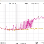
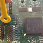
I recently used an inexpensive DTV telescoping dipole antenna to perform some quick troubleshooting. Because I didn’t have any gear with me when a client called (I was on vacation). I stopped at a hardware store to get an antenna and a few other items. We set up the antenna on a workbench and applied some fixes to a noisy DC brush motor. Within two hours, we had reduced emissions by 20 dB. I let the client keep the antenna.
The DTV antenna is advertised to cover frequencies from 54 MHz to 230 MHz (the former VHF analog TV channels 2 to 13) and 470 MHz to 806 MHz (the former analog UHF TV channels 14 to 69). The antenna is matched to 75 Ω, which means you’ll have to adapt the “F” connector to BNC (Figure 4). Most RF measurement equipment is designed for 50 Ω, but some may be switched to 75 Ω inputs. For the purposes of troubleshooting, you can ignore the 75 Ω to 50 Ω mismatch.

RG-59/U (75 Ω) coax cable can be quite stiff, so you may wish to replace it with a more flexible 50 Ω RG-58 or RG-174/U coax. Because of the 75 Ω-to-50 Ω mismatch between the antenna cable and the spectrum analyzer’s 50 Ω input, you’ll probably get reflections and corresponding common mode currents reflecting through the cable. To alleviate any measurement errors, you can add one or more ferrite chokes along the cable to help block these common-mode currents.
The base is also a bit narrow, which makes the antenna rather unstable with the telescoping elements fully deployed. Taping it down to a solid surface can help.
PC-board antennas
One of my favorite antennas for troubleshooting is the PC board design by Kent Britain of Kent Electronics, which sells several off-the-shelf and custom PC board antennas. I ordered three types of log periodic (LP) antennas that together cover 400 MHz to 11 GHz (Figure 5). Total cost: $68.

When the antennas arrived, I installed suitable PC-mount SMA connectors at the tips — mounting each on the “ground” side of the array and running the coax cable straight down the center.
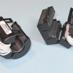
Needing the ability to disassemble and store the antennas and a small table-top tripod in my troubleshooting kit, I used a standard 3/4-in. PVC pipe. Figure 6 shows the parts, which include a right-angle adapter and a base cap. I drilled and tapped a 1/4-20 thread into the base cap, which now can screw onto an everyday photographic tripod. Next, I screwed the right-angle adapter to the cap and hand-tightened them.

I carefully cut a slot into the horizontal pipe using a hand saw. With the slot cut, I then press-fit the antenna into the slot. If the press fitting the antenna doesn’t hold it in place, then use some glue. I then pressed the horizontal pipe to the right-angle adapter. Doing so lets me rotate the antenna for horizontal or vertical polarization. See the completed antenna in Figure 1.
I use a table-top T-Pod tripod from Trek-Tech. It’s no longer available, but you can purchase similar tripods online. Most tripods collapse and often come with a pouch for storage. The T-Pod sections connect with strong neodymium magnets, making them strong enough to easily hold the antenna. Look for a tripod that lets you raise the antenna height to best position it, or you may need to place the antenna and tripod on a table to get the needed height.
Unfortunately, the 400 MHz-to-1000 MHz LP antenna isn’t specified for frequencies down to 100 MHz. If it was, then it wouldn’t fit in my Pelican 1510 roller case. According to Kent, the size was at least partly limited by the maximum panel size that his PC board fabricator used. The good news is that the antenna will work well enough down to 100 MHz for troubleshooting purposes. After all, if you can see the offending frequency on a spectrum analyzer, you can fix it.
Summary
Combined with a spectrum analyzer, a set of Kent Electronics PC board antennas or a DTV antenna lets you perform radiated emissions troubleshooting in-house. These antennas should save you considerable money and time in getting products to comply with EMC regulations without repeatedly visiting a third-party compliance test lab. You’ll find in-house testing a huge advantage.
References
Wyatt, PC Board Log-Periodic Antennas (EDN).
Create Your Own EMC Troubleshooting Kit (Volume 1), by Kenneth Wyatt, available through Amazon.

I have this combination log-periodic/rabbit-ear TV antenna. Does having the two antennas help?
