EE World gets its hands dirty on the latest Tektronix oscilloscope. So many features, so little time.
When Tektronix gave the press a preview of the 4 Series B 12-bit mixed-signal oscilloscope and TekScope software, I asked to try the software. Days later, the real thing arrived in a transit case. Fortunately and unfortunately, today’s oscilloscopes have so many features that you can’t try them all in just a few days. Here’s what I tried (on a fully loaded MSO46B) and how having an unexpected in-person demonstration answered important questions.
Successor to the 4 Series A, the 4 Series B boasts a more powerful processor, a more responsive user interface, and faster data processing. Not having a 4 Series A unit to compare, I’m not qualified to comment on the differences — Tektronix provided a fully loaded 12-bit MSO46B. It has six channels (there’s also a four-channel variant), a 1.5 GHz bandwidth, 62.5 Gsamples of acquisition memory, and a power-analysis option. The price is somewhere around $35,000. A four channel model with 200 MHz bandwidth has a starting price of $8830. Bandwidth is field upgradable.
The 4 Series B has far too many features to learn and explore in the short time I used it. The video below provides a quick tour. In the second video, I was fortunate to record an in-person tradeshow demonstration of the oscilloscope’s two ways of viewing signals in the frequency domain.
For this tryout, I looked at analog and digital signals to get a feel for how to use the instrument. Analog signals covered frequencies from audio to 50 MHz. That hardly stresses this 1.5 GHz oscilloscope, but it’s enough to explore it. Let’s take a tour of the screen in Figure 1.

Start with a basic signal
When you connect a Tektronix probe to an oscilloscope channel, its icon appears at the bottom left of the screen. Here, channel 4 is highlighted while other channels are shaded, which indicates that they are not displayed but are still active. A single tap or click expands the analog channel box; two icons let you adjust the channel’s vertical scale. A double click or tap opens a dialog box with more detail, including the ability to turn off the channel from the display.
Moving to the bottom center of the screen, buttons let you add math traces, a reference trace, bus decode, DVM settings, and function-generator settings. You can activate the DVM once you register the oscilloscope with Tektronix. You’ll have to pay to activate the function generator, bus decode, and other options.
The “Horizontal” box on the right lets you adjust the oscilloscope’s time axis, which you can also do from the scale and position knobs. The box provides time-per-division, time across the screen, sample rate, time per point, number of points, and the relative location of the trigger point, here shown as 46% relative to the left edge. The trigger box, when fully open, lets you select from many trigger types and set parameters such as voltage level, pulse width, and runt.
The upper left shows additional features such as cursors, measurements, and a results table. The More button opens a menu that lets you select zoom, visual trigger, mask, or Waveform histogram. Finally, the dotted box lets you draw a box around a portion of the screen and set up a conditional trigger with the box area only. I used that to get a trigger on an intermittent USB signal.
Clicking on the three vertical dots on the right side of the grid lets you hide the box and expand the grid.

Digital signals: USB
For digital signals, I used USB signals from a keyboard and from a demo board that Tektronix provided. Why a keyboard? Because I can easily choose when to send data over the bus. The supplied passive probes have a 1 GHz bandwidth, but that’s not realistic given the connection through a grounding clip. Tektronix does provide ways to connect the probe with shorter connections. Figure 2 shows a modified demo board (at a tradeshow booth) with a connector that eliminates the clip-on probe lead, vastly improving signal integrity.
To get access to the USB signals from the keyboard, I used a universal USB breakout board (Figure 3), available from Amazon, which has every type of USB connector. I soldered wires to the through holes and clipped probes to the D+ and D- lines. A USB keyboard uses low-speed, single-ended signals. USB 2.0 Full-Speed signals require a differential probe. You can make a differential probe using two channels and subtracting one channel from the other.

The USB keyboard signal would occasionally show an additional set of pulses, which can be difficult to keep on the screen. In Figure 4, those pulses occur during the long period where D+ (Ch 1, yellow trace) is low, and D- (Ch 2, blue trace) is high. To get a stable display, I drew a box approximately where the pulse train starts and set an edge trigger inside the box. I then dragged the box with my finger to find the first rising edge. That helped, but a better way was to set a pulse-width trigger in the box. That produced a stable display.

Although the amplitudes of the pulses in Figure tek_USB_kbd_data_001 look the same, there are differences, which the histogram feature in Figure 5 highlights. That’s where using the Measure tool helped.
Analog, digital, and power
USB power delivery requires handshaking to find a match between the source and load. To get a view of the signals, I used a USB-C breakout board and connected an iPhone to a Momax Airbox Go wireless power bank, though I used its USB-C wired connection only.


Figure 6 shows the VCC line (top trace) and the CC1 line (bottom trace). Unplugging the iPhone shows considerably more activity. Figure 7 shows a series of pulses on the CC1 line and some activity on the differential USB 2 D+ and D- signals. Here, the middle trace subtracts Ch5 from Ch6. These represent the D+ and D- lines, respectively, where two single-ended probes combine to form a differential probe for the math trace.

Bus decode
Like many oscilloscopes, the 4 Series B units have an optional bus-decode feature. The long list of buses that it can decode includes USB 2.0, SPI, I3C, SENT, and RS-232. The datasheet lists them all. To enable bus decode, simply touch or click on Add New Bus at the bottom of the screen. A dialog box that lets you choose the bus and select how to trigger the oscilloscope on a bus characteristic. The bottom of Figure 8 shows the decode feature based on USB from the keyboard. The demo board also provides USB signals to decode. I also tried decoding an RS-232 signal from the demo board. For the keyboard decode, I first triggered on the pulse width in the box described above, then changed the trigger to act on a USB sync pattern. Figure 9 shows the menu.


Digital, in the frequency domain
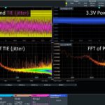
While using the MSO46B, I discovered that it has two ways to convert time-domain signals into the frequency domain. The oscilloscope has the usual FFT math function, which calculates frequency after acquiring a time-domain signal. You can find that under the More menu on the right side of the screen.
The second method, which Tektronix calls Spectrum View, is one of several pull-downs in the channel dialog box. Spectrum view operates in real-time as opposed to post-processing.

Figure 10 shows a spectrum view though it doesn’t demonstrate the feature’s usefulness. See the video below for an in-person demonstration at a trade show that shows how the oscilloscope demodulates the frequency deviation from a spread-spectrum square wave. You can even trigger the oscilloscope on the waveform representing the frequency deviation. According to EE World contributor Kenneth Wyatt, who wrote an application note that discusses frequency domain triggering for EMI troubleshooting, frequency domain triggering is unique to Tektronix. It’s a handy feature.
Save and restore
Because you always need to document your work, the Tektronix 4, 5, and 6 Series oscilloscopes let you save screen images, but that’s not all. The oscilloscopes let you save setups, waveform data, and complete sessions through their File menu. If you save trace data and recall it, you’ll see it on the screen, and you can keep it on the screen to compare the trace to a later acquisition. That lets you see the effects of design changes, which is quite useful. For this tryout, I saved screen images, waveform data, and setups. Following the live demonstration in the video above, I learned the usefulness of saving a session, which lets you save both setup and waveform data at the same time. Recalling a session brings back both and replays the session. You can’t do that with a lab notebook.
When saving the data from more than one waveform, pay attention to the source selection. When I recalled a set of waveforms, only one appeared because only one was saved. You can, however, choose which traces (channel or math) to save as waveform files. If you select more than one trace, the oscilloscope will save each trace as a separate wfm file. Thus, you need to recall more than one file to see the traces. The oscilloscope also lets you recall waveforms captured on competitors’ oscilloscopes.
TekScope and TekCloud
Having the ability to save waveforms or sessions to analyze signals is useful, but what happens if you relinquish the instrument to a colleague or use it in another project? You have several options for moving data to a PC for offline analysis.
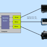
Because digital oscilloscopes include connectivity, you can control the instrument from a purchased app, or you can develop your own. Tektronix offers TekScope, a Windows app that emulates the instrument on a PC where the PC screen operates identically to the instrument’s screen. You lose the knob controls, of course. TekCloud lets you store data to the cloud where you can retrieve data to a PC or to the oscilloscope. Tektronix provided a license for its Ultimate TekScope 2.4 version. I installed TekScope on my PC connected to the MSO46B and installed the license, which you must place on your PC and then give TekScope the location to activate it.
You can connect the oscilloscope directly to a PC through its rear-panel USB-A port or over a LAN to store and transfer data to or from TekCloud. I didn’t try the LAN option because I didn’t want to connect anything that someone had used before to my network.
Connecting the oscilloscope to my Windows 10 desktop over USB didn’t go well, for the instrument never came online. I suspect a conflict occurred because the PC sometimes uses a PC-based instrument that loads its software whenever you connect it. When the initial installation of TekScope didn’t connect, I tried installing TekVISA, a software layer used as an API between an instrument driver and the operating system. After installing TekVISA, my PC showed a popup window informing me that a TekVISA resource was added or removed whenever I connected or disconnected the oscilloscope. Checking the Windows Device Manager showed that the PC recognized the oscilloscope, but it remained offline in TekScope. Fortunately, a USB flash drive let me transfer data from the instrument. You can have connection issues if you install more than one company’s VISA on the same PC, but I couldn’t find any other VISA versions.
Conclusion
The MSO46B is a powerful instrument. I do have some suggestions for the C version. For example, when enabling the cursors, only the vertical lines appeared. That’s fine for measuring the time between two events, but what about the horizontal lines for measuring amplitude differences? They’re not missing, but to view them you must tap or click on a blank area of the screen. I learned that by asking at the live demonstration. There should be a way to turn both horizontal and vertical cursors on or off from the cursor menu.

Tapping on a blank screen area also helps if you find the type in the dialog boxes too small to read clearly. From there, you can zoom in or out, which makes the text easier to read. Of course, you can also connect an external monitor to the oscilloscope’s HDMI port. Tapping on a blank area also lets you set the screen persistence.

Because I used rear-panel USB ports and the function-generator’s BNC connector, I sometimes had to hunt around to find them unless I turned the instrument around. I didn’t want to simply tilt the instrument forward for fear of breaking the probes. To make the connectors easier to find, I placed a strip of tape (Figure 11) along the top of the case and marked to locations of all rear-panel ports. Tektronix should consider adding some screen printing pointing to the connectors.
Tektronix still includes the most important feature: a slot for a laptop lock (Figure 12), though many laptops no longer have them. After all, you don’t want colleagues removing your oscilloscope from your bench.


Rumor has it that I’ve emerged from the basement. It’s true. The oscilloscope was shipped back to Tektronix on December 20.
What was the hard part? Soldering the wires to the breakout boards. I’m too old and now need an over-the-head magnifier. Otherwise, my face would get close enough the the iron to feel its heat. That’s too close for comfort.
Have you tried a 4 Series B oscilloscope? Do you use a 4 Series A model?