The 5G realm puts a new emphasis on making measurements without hardwired connections.
Adnan Khan | Anritsu Co.
5G systems are being rolled out globally, bringing with them throughput speeds of up to 10 Gbps, higher frequencies that extend into the millimeter wave (mmWave) spectrum, and devices operating in multiple radio access technologies (RATs). Engineers are faced with considerable design challenges in 5G. Among these challenges is the stringent testing associated with chipsets, devices, and systems.
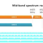
Over-the-air (OTA) testing approaches are becoming the norm for testing 5G New Radio (5G NR) user equipment (UE) and base stations, especially in mmWave. The move to higher frequencies, including sub-6 GHz Frequency Range 1 (FR1) and mmWave Frequency Range 2 (FR2), arises in large part to the crowding of the RF spectrum. For these reasons, 5G NR networks and UE devices require advanced technologies and OTA measurements to characterize performance accurately.

For a given transmit power level, mmWave signals do not travel as far as lower-frequency RF/microwave signals. The free space propagation loss is a square function of the frequency and distance.
For maximum signal propagation distances, 5G NR systems must direct signal energy between network nodes and UE devices, using active antenna systems (AAS), beamforming, and high-speed signaling techniques. 4G LTE and earlier wireless generations transmitted signal energy in all directions, for a 360° signal around a base station at relatively high transmit power levels compared to 5G NR systems. Operating at mmWave frequencies with lower transmit power levels, 5G networks have considerably more base stations for proper coverage.
Antenna arrays
Directional signal beams in 5G NR systems are transmitted and received using antenna arrays. Rather than the omnidirectional signal energy transmitted in a 4G LTE system, a 5G NR device will locate a 5G NR base station within range by receiving an identifying signal from the base station. Signaling between the base station and UE will establish the coordinates for directed energy beams formed by antenna arrays in the base station and device. As such, there can be a communication beam in the Uplink (UL) and a separate one in the Downlink (DL).

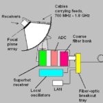
A 5G base station is two subsystems – a baseband controller unit and a remote radio head (RRH) – that are connected by a fiber-optic cable. The RRH contains a highly integrated transceiver (TRX) and AAS. 5G NR base stations are smaller and have lower power compared to 4G LTE towers.
The size of the antenna is also inversely proportional to the operation frequency. As such, at 28 GHz or 39 GHz, an 8×8 patch antenna array may be 5 cm or smaller. It’s physically not possible to have a connectivity port on the antenna in mmWave. Also, the loss if a cable is connected will be significant. Neither the Base Transceiver Station (BTS) or UE can have a test connectivity port at mmWave. Hence, testing in an OTA environment becomes a necessity for proper RF characterization and performance analysis.
Advanced AAS circuits in 5G radio equipment try to maximize propagation distances at mmWave frequencies where signal energy is limited (and more expensive than at lower frequencies). 4G LTE leverages multiple-input, multiple-output (MIMO) antenna approaches to overcome signal path losses and enhance throughput and capacity. 5G NR networks use multiple AAS units in massive MIMO configurations to direct mmWave energy through space as efficiently as possible.
An AAS consolidates separate antenna elements, such as an 8×8 array with 64 elements. Each element has controllable amplitude and phase adjustments. Because each element is individually controllable, it becomes increasingly important for testing to calibrate and characterize the antenna array elements so they properly align with frequency and time. This ensures the contributions of the many antenna elements combine to form and “steer” an energy beam in a desired direction precisely. 5G systems have multiple arrays in massive-MIMO configurations for peak use of available signal power at mmWave frequencies.
Using advanced signaling techniques, a 5G network node provides a beacon signal for a 5G device in range to identify and synchronize. There are different techniques, such as analog beamforming, digital beamforming, and hybrid beamforming, that are utilized depending on the applications.
Significant digital processing is applied in 5G NR signal switching to find the optimum signal path between a base station and a UE to save energy. Signal processing is particularly important at mmWave frequencies where the smaller-wavelength signals suffer reflections from solid objects, such as building walls. There are other losses that the system must be designed to mitigate or handle, such as penetration, reflection, diffraction, foliage, and atmospheric losses.
Reflection, free-space loss and diffraction (e.g., the bending of rays around building corners/roofs) loss rises with frequency. Smaller objects, like lamp post surfaces, are more reflective as frequencies rise but seem to make up for loss in diffraction in outdoor environments. Lower frequencies, such as 3.5 GHz, are used for high-coverage lower data rate, while 24 GHz, 28 GHz, and 39 GHz frequencies are allocated for low-latency, smaller coverage, and high-speed data transfers.
Measurement challenges

Although these advanced antenna techniques make high-speed communications practical for 5G systems at mmWave frequencies, they add complexity to testing. Antennas designed into devices are miniature and tightly integrated with TRx circuitry, making RF probing at points between TRx and antenna circuits impractical. Fortunately, by OTA testing in the far field of a 5G UE device’s antenna, a 5G UE device can be fully characterized.
A typical OTA measurement environment places the 5G UE device in an EM-shielded chamber to eliminate outside interference. Measurements of the DUT’s antenna radiation pattern take place in the test chamber using an antenna with enough frequency range and performance capabilities.
Because measurements of 5G devices take place on antenna arrays, multiple radiation beams are formed close to the individual elements, combining to configure a directed beam further from the array structure. Closer to an antenna (near-field region), the radiation pattern has a spherical shape. Moving further from the antenna (far-field region), the radiation pattern has more of a planar shape. Within the far field is a “quiet zone” where the radiation pattern is most stable and consistent. It is the best location for a test antenna.

The distances of near fields and far fields from different antennas and arrays are a function of many variables. Some of the more notable are antenna size, array element size, and spacing between elements, frequency and wavelength.
To prevent the test antenna within a shielded enclosure from contributing its own characteristics to the measurement of a DUT’s radiation patterns, OTA measurements are performed in the far fields of both antennas. Ideally, for access to the highest amplitude levels from a DUT, the test antenna is placed as close as possible to the beginning of the DUT’s far field.
Choosing an OTA measurement approach involves understanding measurement conditions. A DUT’s far field needs to fit within the test chamber. It must also feature a test setup that can perform measurements with enough range, accuracy, and speed to make 5G UE measurements practical. The most common OTA test approaches are indirect-far-field (IFF), direct-far-field (DFF), and near-field-to-far-field (NFTF) configurations.
IFF – Also known as a compact antenna test range (CATR), IFF uses a shaped reflector to collimate beams from a DUT and effectively shorten the distance to the far field. It has less path loss than the longer distance to the far field in a DFF setup. The trade-off is that it can only measure one signal at a time as it has a single feed antenna. IFF typically has a positioner to move the azimuth and elevation of the DUT to create a 3D radiation pattern for testing.
DFF – Like IFF, DFF uses a positioner to adjust the DUT azimuth and elevation to create a 3D radiation pattern for testing. Unlike IFF, this chamber can have multiple feed antennas, hence, enabling multiple measurements with different angle of arrivals. This method can result in significant savings in terms of OTA chamber capital cost, as it does not use the reflector.
NFTF – With this approach, measurements are first made in the DUT’s near field. Fast-Fourier-transform (FFT) calculations then predict far-field data from the near-field measurements. This is the slowest of the three OTA approaches because of the test and computation times required.
OTA testing helps to ensure 5G UE are in compliance with Third Generation Partnership Program (3GPP) standards. Among the critical measurements for 3GPP acceptance are effective isotropic radiated power (EIRP), total radiated power (TRP), effective isotropic sensitivity (EIS), and total isotropic sensitivity (TIS).
EIRP determines how much power an omnidirectional antenna needs to transmit in all directions to match the signal strength of a directional antenna in one direction. EIS measures the sensitivity of an antenna to detect signal energy in one direction. EIRP and EIS measurements can provide details on locating the beam peak transmitted by a UE device and its sensitivity to detecting the identifying beam transmitted by a 5G network node, base station, or “hot spot.”
OTA measurements require a test chamber based on a designated OTA test method. The reference antenna and test equipment must measure frequency, power, spurious emissions, and error vector magnitude (EVM) of in-phase/quadrature (I/Q) modulated signals in FR1 and FR2 frequency bands to capture higher-order harmonic interference. The proper test setup will include a signaling tester that can act as a 5G NR network node (5G nGB) when testing a UE device within the test chamber.
OTA measurements on 5G devices pose new test challenges, including evaluating DUTs with multiple RATs, multiple frequency ranges, and advanced AAS architectures. Because of the complexity of beam forming and signal switching in 5G systems, a measurement system must also serve as a 5G nGB.
The test solution must provide control of signal frequency and power and evaluate how a 5G UE DUT responds to different signal and beam-switching environments. Because some conformance tests for 5G UE are still in development, the 5G NR test environment is still changing and will benefit from a test solution that can efficiently evolve as standards advance.
Test equipment for 5G UE device testing should provide performance levels that exceed those expected of a DUT, in terms of frequency range, frequency accuracy, signal sensitivity, and dynamic range. The measurement uncertainty of the test equipment should be well within the limits of applicable measurement standards and the performance limits of the DUT. Engineers must consider that uncertainty is impacted by the test antenna calibration, DUT positioner, and the frequency accuracy of the test system’s reference oscillator.
In a nutshell, the integration of mmWave frequencies, coupled with the exponential increases in bandwidth and latency associated with 5G, have made OTA testing an essential part of the verification process. Selecting the proper test solutions and OTA approaches can improve product design and speed time-to-market.


what are main 5G field measurement parameter that can be measured