Phase noise requires more than one instrument unless you use a phase-noise analyzer.
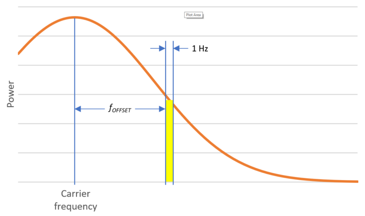
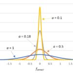
In part 1, we discussed how phase noise is specified in decibels per hertz relative to the carrier (dBc/Hz) at a specified offset frequency fOFFSET. Essentially, phase noise is the power in the yellow 1-Hz-wide rectangle in Figure 1 relative to the carrier power.
Can I just use a spectrum analyzer to measure phase noise?
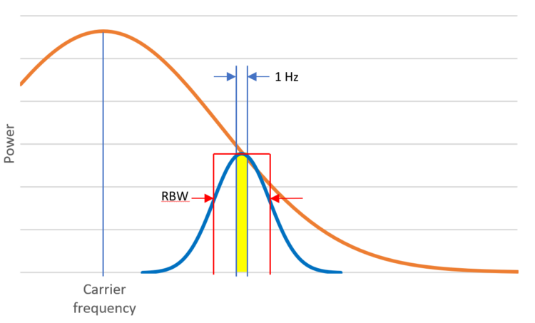
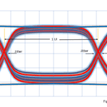
Yes. A spectrum analyzer is a useful general-purpose instrument found in many engineering laboratories. There are, however, a couple of issues you should keep in mind when using a spectrum analyzer to measure phase noise. For example, your spectrum analyzer may not have a 1-Hz resolution-bandwidth (RBW) filter, and even if it does, the filter’s response certainly won’t be rectangular—it’s more likely to be Gaussian, as shown by the blue curve in Figure 2.
You can account for the RBW being greater than 1 Hz by a process of normalization — that is, adjusting a power measurement in a 100-Hz band, for instance, to reflect the power in a 1-Hz band. Because we are dealing with power levels in decibels, we simply subtract 10 times the base-10 logarithm of the RBW in hertz from the measured power value at fOFFSET. For example, if your spectrum analyzer tells you the value is -60 dBc at fOFFSET and RBW is 100 Hz, then your normalized phase noise is as follows:

You will also need to correct for the difference between the RBW filter’s gaussian shape and the ideal rectangular characteristic outlined in red in Figure 2, and you may not have enough information about the RBW filter’s exact output characteristic to do that accurately. Fortunately, many spectrum-analyzer vendors offer phase-noise-measurement applications for their instruments that automate the normalization and shape-correction processes.
What else should I know about using a spectrum analyzer to make phase-noise measurements?
You might encounter a couple of situations in which spectrum analyzers provide less than optimal results. For example, although phase noise is often more of a problem than amplitude noise, you may have significant amplitude noise that must be distinguished from phase noise. The spectrum analyzer method won’t do that, and you will need a phase detector. Keysight offers an application note that describes three phase-detector techniques, including a reference-source/phase-locked-loop method as well as analog and digital frequency-discriminator methods.
In addition, note that when you are using a spectrum analyzer to measure phase noise, you are not just measuring the phase noise of your device under test (DUT)—you’re also measuring the phase noise of the local oscillators (LOs) in the spectrum analyzer. If your spectrum analyzer has much lower phase noise than your DUT, this won’t be a problem. But if your DUT is an oscillator for a high-end spectrum analyzer, you may have a problem.
But there is a workaround, right?
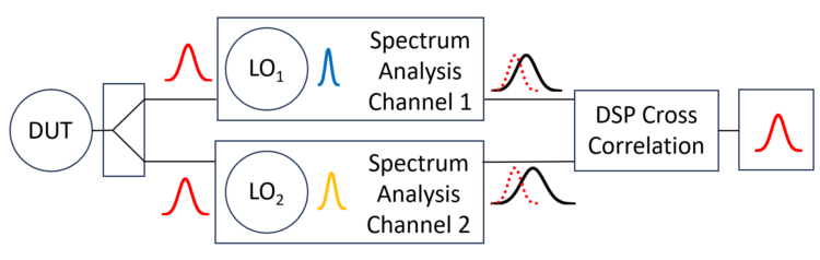
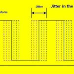
Right. Figure 3 shows a DUT output connected to a splitter, which delivers two nearly identical highly correlated inputs (red waveforms) to two spectrum-analysis channels, each with an independent LO that contributes its own phase noise (sletched as blue and orange waveforms). Each channel’s output is illustrated by a black waveform overlaid with the dotted red input signal, suggesting the phase noise added by the LOs. We take advantage of the fact that the independent LOs’ outputs are uncorrelated, so we can use digital signal processing (DSP) to execute a cross-correlation function to minimize their contributions, resulting in an accurate representation of the DUT’s output.
So I need two spectrum analyzers?
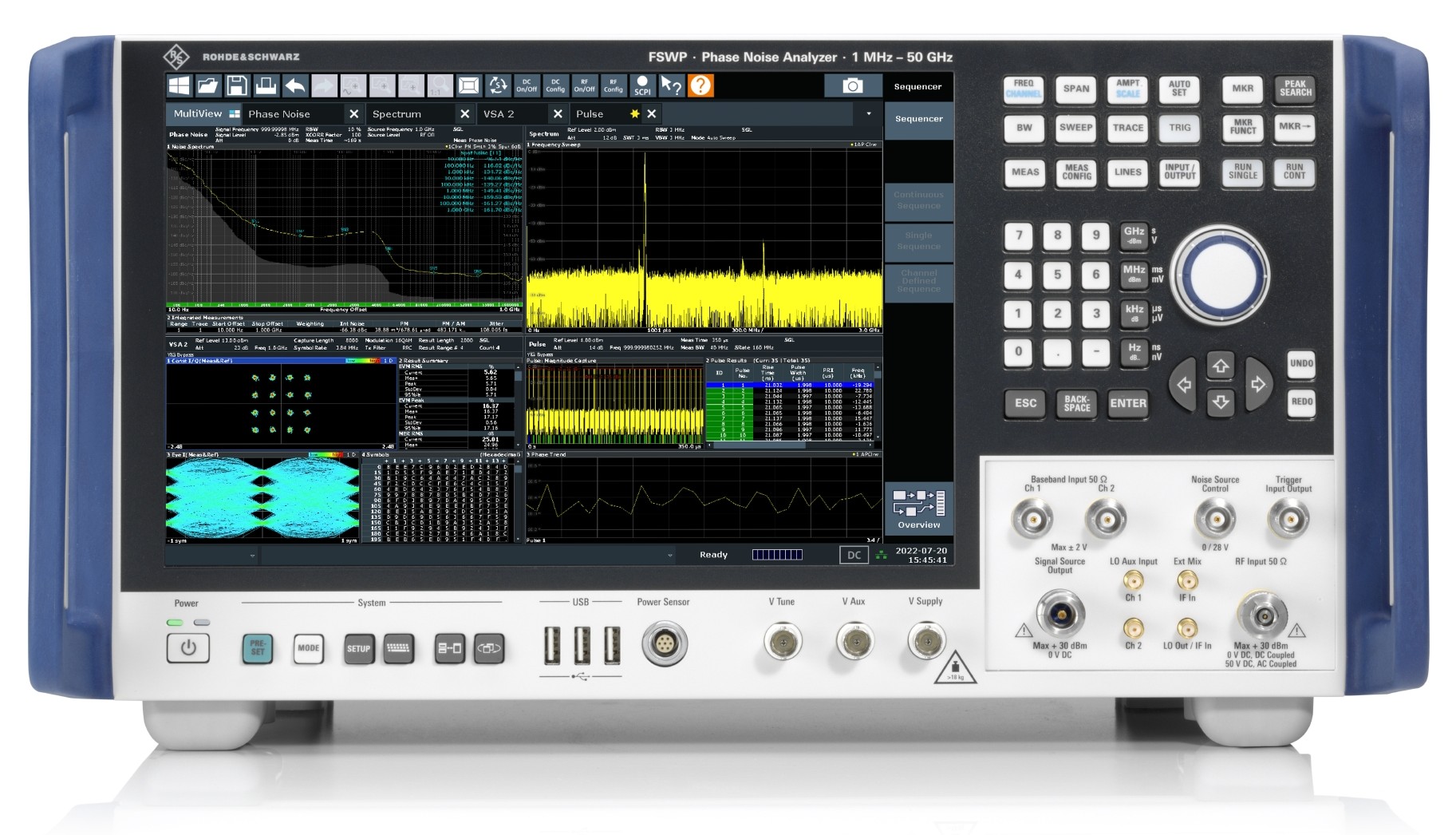
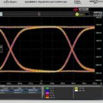
And a DSP engine that can run the cross correlation. An alternative is to choose a specialized instrument that can perform operations such as cross correlation and phase detection. Examples include the Keysight E5052B signal-source analyzer and the Rohde & Schwarz FSWP phase-noise analyzer and voltage-controlled oscillator (VCO) tester (Figure 4).
In addition to reading the Keysight application note you cited, where can I learn more?
Rohde & Schwarz is offering a series of webinars on phase-noise measurement. The first installment on December 13 covered the fundamentals, including normalization, shape correction, and cross correlation. An installment scheduled for January 18 will cover measurement techniques. For more information and to register for the next session, click here.


Leave a Reply
You must be logged in to post a comment.