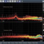
A simple oscilloscope setup can size common-mode and differential-mode noise filtering components separately and more accurately. Marcus Sonst, Rohde & Schwarz Any switched-mode power supply (SMPS) needs an EMI (electromagnetic interference) input filter to avoid disturbing power lines. Input filters generally contain both common-mode and differential-mode filter elements, and the two are rarely optimized separately. […]
oscilloscope measurements
A day in the life: Five RF measurements for field engineers
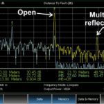
A handful of basic techniques go a long way toward characterizing modern communication systems. Sarah Gross, Keysight Technologies Field engineers often find that every day presents its own special challenges. A typical work day may involve measuring a variety of devices or signals — cables, antennas, over-the-air 5G signals, or intermittent spurious signals. Successful completion […]
Single-sideband modulation and its measurement
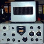
The most basic form of amplitude modulation is known as double-sideband AM, so called because mirror-image sidebands are produced above and below the carrier frequency. Early researchers found that they could use simple band-pass filters to eliminate one of the sidebands and even the carrier signal, improving the ratio of information-bearing power to total transmitted […]
Integration and differentiation operations and how they appear on a scope

Differential calculus is the study of rates at which quantities change. To find the derivative of a waveform at a specific point, we draw a tangent line through the point. The slope of the line, Δy/Δx, equals the derivative of the function at that point. Integral calculus quantifies the area bounded by a curve and […]
Scope test setup complies with IEEE 802.3ch MultiGBASE-T1 Automotive Ethernet standard

The new K88 option for R&S RTO and R&S RTP oscilloscopes from Rohde & Schwarz enables compliance testing on the next evolution of the automotive Ethernet standard. The new IEEE 802.3ch standard addresses the need for high speed networking and data transfers within the car. With the K88 software option, Rohde & Schwarz continues to […]
Rack-mount scope integrates spectrum analyzer, AWG, DVM, frequency counter/totalizer, serial protocol analyzer
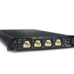
The Rigol DS8000-R Series four-channel digital oscilloscopes are compact 1U half-rack-width instruments available in 350 MHz/1 GHz/2 GHz versions with a maximum sampling rate of 10 GSa/sec. In addition to their use installed in a test rack cabinet, these instruments can be conveniently used on a workbench. The DS8000-R series has been designed around RIgol’s […]
What is a load coil and how do you measure it?
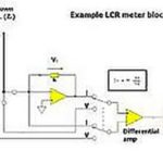
The textbook description of an inductor often involves a coil of wire. Of course, any material other than a perfect ideal insulator has theoretical inductance. All the windings do is multiply the effect by creating overlapping fields. It’s good to keep in mind that inductance is measurable in many non-coils, such as power transmission lines, […]
Trigger-and-decode scope setup handles 1000BASE-T1 automotive Ethernet
The new K58 option for R&S RTO and R&S RTP scopes is billed as the world’s first triggering and decoding solution for 1000BASE-T1. The flexibility of Automotive Ethernet makes the simple twisted-pair network technology a candidate for an ever-increasing range of in-vehicle networks. To verify, commission and troubleshoot designs based on an Automotive Ethernet communication […]
IEEE 802.3ch multi-gigabit Ethernet compliance setup covers PMA transmitter tests

The TekExpress Multi-Gigabit Automotive Ethernet Compliance Test Solution is billed as the first-in-market solution to meet the requirements of complex automotive designs. As newer automotive technologies such as autonomous driving, 5G and connected car solutions develop, the paths carrying the vast amount of data necessary to support those technologies must be tested to ensure reliable […]
Don’t get zapped — Using test instruments safely

Most engineers think they’ve minimized the chance of nasty surprises around the test bench when they’ve grounded their instruments and perhaps kept one hand in their pocket when working around high voltages. That said, there remain electrical hazards that are less obvious. They involve the electrical wiring and the environment around the lab. To begin, […]
